NOTE: where the broadcom document uses addresses 0x7420xxxx, you'll use 0x2020xxxx.
给出的提示要求我们在赋值时采用位运算:
1
2
3
4
5
// assume: we want to set the bits 7,8,9 in <x> to <v> and
// leave everything else undisturbed.
x&=~(0b111<<7);// clear the bits 7, 8, 9 in x
x|=(v<<7);// or in the new bits
而不是简单的直接赋值,主要是考虑到多个 LED 同时控制的情况,可以自行尝试直接赋值控制多个LED。
/*
* write code to allow blinking using arbitrary pins.
* Implement:
* - gpio_set_output(pin) --- set GPIO <pin> as an output (vs input) pin.
* - gpio_set_on(pin) --- set the GPIO <pin> on.
* - gpio_set_off(pin) --- set the GPIO <pin> off.
* Use the minimal number of loads and stores to GPIO memory.
*
* start.s defines a of helper functions (feel free to look at the assembly! it's
* not tricky):
* uint32_t get32(volatile uint32_t *addr)
* --- return the 32-bit value held at <addr>.
*
* void put32(volatile uint32_t *addr, uint32_t v)
* -- write the 32-bit quantity <v> to <addr>
*
* Check-off:
* 1. get a single LED to blink.
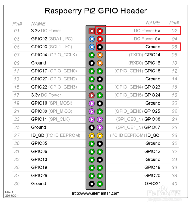
* 2. attach an LED to pin 19 and another to pin 20 and blink in opposite order (i.e.,
* one should be on, while the other is off). Note, if they behave weirdly, look
* carefully at the wording for GPIO set.
*/// these are in start.s
voidput32(volatilevoid*addr,unsignedv);//void PUT32(int addr, unsigned v);
unsignedget32(constvolatilevoid*addr);//unsigned GET32(int addr);
voiddumpy(intaddr);// see broadcomm documents for magic addresses.
#define GPIO_BASE 0x20200000
volatileunsigned*gpio_fsel0=(volatileunsigned*)(GPIO_BASE);volatileunsigned*gpio_fsel1=(volatileunsigned*)(GPIO_BASE+0x04);volatileunsigned*gpio_fsel2=(volatileunsigned*)(GPIO_BASE+0x08);volatileunsigned*gpio_set0=(volatileunsigned*)(GPIO_BASE+0x1C);volatileunsigned*gpio_clr0=(volatileunsigned*)(GPIO_BASE+0x28);// set <pin> to output. note: fsel0, fsel1, fsel2 are contiguous in memory,
// so you can use array calculations!
voidgpio_set_output(unsignedpin){// use gpio_fsel0
intFSEL_offset=pin/10;//*gpio_fsel1 = (0b001 << 18);
volatileunsigned*gpio_fsel;switch(FSEL_offset){case0:gpio_fsel=gpio_fsel0;break;case1:gpio_fsel=gpio_fsel1;break;case2:gpio_fsel=gpio_fsel2;break;default:gpio_fsel=gpio_fsel0;}*gpio_fsel&=~(0b111<<((pin%10)*3));*gpio_fsel|=0b001<<((pin%10)*3);// set the pin outset <pin> on.
}voidgpio_set_on(unsignedpin){// use gpio_set0
*gpio_set0=1<<pin;}// set <pin> off
voidgpio_set_off(unsignedpin){// use gpio_clr0
*gpio_clr0=1<<pin;}// For later labs, write these routines as well.
// set <pin> to input.
voidgpio_set_input(unsignedpin){// use gpio_fsel0
intFSEL_offset=pin/10;volatileunsigned*gpio_fsel;switch(FSEL_offset){case0:gpio_fsel=gpio_fsel0;break;case1:gpio_fsel=gpio_fsel1;break;case2:gpio_fsel=gpio_fsel2;break;default:gpio_fsel=gpio_fsel0;}*gpio_fsel&=~(0b111<<((pin%10)*3));*gpio_fsel|=0b000<<((pin%10)*3);// set the pin outt <pin> to <v> (v \in {0,1})
}voidgpio_write(unsignedpin,unsignedv){//
return;}// countdown 'ticks' cycles; the asm probably isn't necessary.
voiddelay(unsignedticks){while(ticks-->0)asm("add r1, r1, #0");}/*
void reboot(void) {
const int PM_RSTC = 0x2010001c;
const int PM_WDOG = 0x20100024;
const int PM_PASSWORD = 0x5a000000;
const int PM_RSTC_WRCFG_FULL_RESET = 0x00000020;
int i;
for(i = 0; i < 100000; i++)
dummy(i);
PUT32(PM_WDOG, PM_PASSWORD | 1);
PUT32(PM_RSTC, PM_PASSWORD | PM_RSTC_WRCFG_FULL_RESET);
while(1);
}
*/// when you run should blink 10 times. will have to restart the pi by pulling the usb connection out.
voidnotmain(void){intled=16;intled2=20;gpio_set_output(led);gpio_set_output(led2);for(inti=0;i<10;i++){gpio_set_on(led);gpio_set_off(led2);delay(1000000);gpio_set_on(led2);gpio_set_off(led);delay(1000000);}// reboot();
}
/*
* write code to allow blinking using arbitrary pins.
* Implement:
* - gpio_set_output(pin) --- set GPIO <pin> as an output (vs input) pin.
* - gpio_set_on(pin) --- set the GPIO <pin> on.
* - gpio_set_off(pin) --- set the GPIO <pin> off.
* Use the minimal number of loads and stores to GPIO memory.
*
* start.s defines a of helper functions (feel free to look at the assembly! it's
* not tricky):
* uint32_t get32(volatile uint32_t *addr)
* --- return the 32-bit value held at <addr>.
*
* void put32(volatile uint32_t *addr, uint32_t v)
* -- write the 32-bit quantity <v> to <addr>
*
* Check-off:
* 1. get a single LED to blink.
* 2. attach an LED to pin 19 and another to pin 20 and blink in opposite order (i.e.,
* one should be on, while the other is off). Note, if they behave weirdly, look
* carefully at the wording for GPIO set.
*/// these are in start.s
voidput32(volatilevoid*addr,unsignedv);//void PUT32(int addr, unsigned v);
unsignedget32(constvolatilevoid*addr);//unsigned GET32(int addr);
voiddumpy(intaddr);// see broadcomm documents for magic addresses.
#define GPIO_BASE 0x20200000
volatileunsigned*gpio_fsel0=(volatileunsigned*)(GPIO_BASE);volatileunsigned*gpio_fsel1=(volatileunsigned*)(GPIO_BASE+0x04);volatileunsigned*gpio_fsel2=(volatileunsigned*)(GPIO_BASE+0x08);volatileunsigned*gpio_set0=(volatileunsigned*)(GPIO_BASE+0x1C);volatileunsigned*gpio_clr0=(volatileunsigned*)(GPIO_BASE+0x28);volatileunsigned*gpio_lev0=(volatileunsigned*)(GPIO_BASE+0x34);// set <pin> to output. note: fsel0, fsel1, fsel2 are contiguous in memory,
// so you can use array calculations!
voidgpio_set_output(unsignedpin){// use gpio_fsel0
intFSEL_offset=pin/10;//*gpio_fsel1 = (0b001 << 18);
volatileunsigned*gpio_fsel;switch(FSEL_offset){case0:gpio_fsel=gpio_fsel0;break;case1:gpio_fsel=gpio_fsel1;break;case2:gpio_fsel=gpio_fsel2;break;default:gpio_fsel=gpio_fsel0;}*gpio_fsel&=~(0b111<<((pin%10)*3));*gpio_fsel|=0b001<<((pin%10)*3);// set the pin outset <pin> on.
}voidgpio_set_on(unsignedpin){// use gpio_set0
*gpio_set0=1<<pin;}// set <pin> off
voidgpio_set_off(unsignedpin){// use gpio_clr0
*gpio_clr0=1<<pin;}// For later labs, write these routines as well.
// set <pin> to input.
voidgpio_set_input(unsignedpin){// use gpio_fsel0
intFSEL_offset=pin/10;volatileunsigned*gpio_fsel;switch(FSEL_offset){case0:gpio_fsel=gpio_fsel0;break;case1:gpio_fsel=gpio_fsel1;break;case2:gpio_fsel=gpio_fsel2;break;default:gpio_fsel=gpio_fsel0;}*gpio_fsel&=~(0b111<<((pin%10)*3));*gpio_fsel|=0b000<<((pin%10)*3);// set the pin outt <pin> to <v> (v \in {0,1})
}voidgpio_write(unsignedpin,unsignedv){*gpio_lev0|=(v<<pin);return;}// countdown 'ticks' cycles; the asm probably isn't necessary.
voiddelay(unsignedticks){while(ticks-->0)asm("add r1, r1, #0");}// when you run should blink 10 times. will have to restart the pi by pulling the usb connection out.
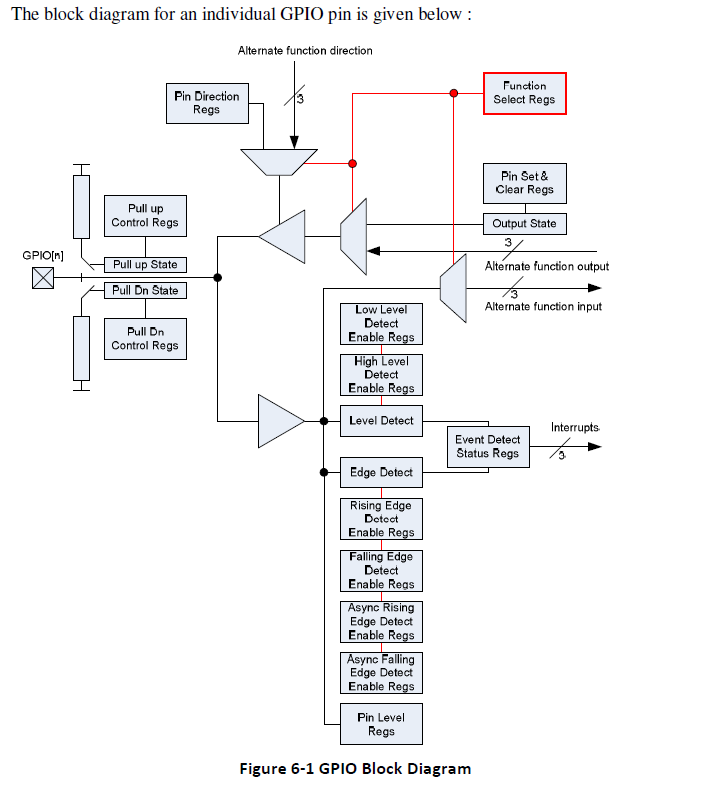
voidnotmain(void){intled_in=20;intled_out=21;gpio_set_output(led_out);gpio_set_input(led_in);volatileunsignedtmp=1<<led_in;// event detected
volatileunsigned*gpio_eds0=(volatileunsigned*)(GPIO_BASE+0x40);// gpio event detect status register0
*gpio_eds0|=(1<<led_in);// high detect enable
volatileunsigned*gpio_hen0=(volatileunsigned*)(GPIO_BASE+0x64);*gpio_hen0=1<<led_in;// low detect enable
volatileunsigned*gpio_len0=(volatileunsigned*)(GPIO_BASE+0x70);//gio_set_output(12);
while(1){*gpio_eds0=tmp;// high level detected
if(*gpio_eds0==tmp&&*gpio_hen0==tmp){*gpio_hen0=0<<led_in;// disable high detected
*gpio_len0=1<<led_in;// enable low detected
gpio_set_on(led_out);// turn on led
}else// low level detected
if(*gpio_eds0==tmp&&*gpio_len0==tmp){*gpio_len0=0<<led_in;// disable low detected
*gpio_hen0=1<<led_in;// enable hign detected
gpio_set_off(led_out);}*gpio_eds0=0;delay(1000000);}}